Operation guide of double cylinder(part 1)
Pageviews: Release Time:2017-09-20
Operation guide of double cylinder(part 1)
A.Main specification


Design drawing of remote control grab
| Crane Lifting Capacity | 25T | |
| 001 | Grab Type | RC25.0-9.5-12.0 |
| 002 | Grab Volume (m³) | 6.0~12.0 |
| 003 | Dead Weight (Kg) | 9500 |
| 004 | Material angle of rest (º) | 30~40 |
| 005 | Density (t/ m³) | 2.5~0.8 |
| 006 | Standard Diameter of the sheaves | 650 |
| 007 | Rate of Sheaves | 3 |
| 008 | Closing Rope-Standard diameter | 36 |
| 009 | Closing Rope-Total Length | 11.2m |
| 010 | Closing Rope-Withdraw to Close | 4587mm |
| 011 | A (mm) | 4689 |
| 012 | B (mm) | 4362 |
| 013 | C (mm) | 2940 |
| 014 | D (mm) | 3953 |
| 015 | E (mm) | 3500 |
| 016 | F (mm) | 5870 |
| 017 | G (mm) | 5540 |
|
|
||
1. Grab Type-RCB(crane lifting capacity)-Density of Materials-Volume(L)
2. The volume in the above table can be adjusted according to the density of the materials,and the volume design can be changable.
3.The above is the standard type of our company,however,can be added or changed according to the customers' requirements.
B.Working Principle
B-1.Structure
The grab is composed by1.Grab Head 2.Transverse Frame 3.Through Beam 4.Press Rods 5.Scoops 6.Control Valve Group 7.Cylinders 8.Steel Wire Rope and so on. (Refer to Pic.1-1)

a. The press rods are connected to the grab head & scoops via axis pins,and the scoops are connected to the through beam via axis pins.
b. The through beam is connected to the cylinder barrels,and the transverse frame is connected to the piston rods;the two cylinders are installed symmetrically
c. The steel wire ropes lift the transverse frame and are installed symmetrically;to increase the grab closing force via pulleys on the grab head and transverse frame.
d. The balancing stand on the transverse frame bear the lifting capacity of the grab,and for avoiding the excessive force to single rope, the two steel ropes adjust mutually.
e. The through beam is a box structure, wholly sealed oil tank in the middle of it, and the control valve group is installed on the cover plate of the oil tank.
B-2.working principle description
Grab Closing: When grab opens, the transverse frame is connected with the grab head but totally separated with the through beam.Solenoid directional valve is closed at this moment. The piston rod of the cylinder is connected with the transverse frame, and the cylinder barrels are firmly jointed with the through beam, so the piston rod of the cylinder is fully extended at this moment. When the grab is loading the bulk materials,steel wire rope of the crane falls and the piston rods draw back for it can move in one-way direction,and then the transverse frame falls. After the piston rods draw back completely,and the transverse frame falls. After that the steel wire rope of the crane rises,and the transverse frame rises with it. As the solenoid valve of the cylinders is always closed,at this moment,the rod cavity & the cylinders are locked.With the pulleys,the transverse frame's rising drives through beam to rise, at the same time,the scoops close.
Grab Opening: When opening the grab, press the button of the remote control to open the solenoid directional valve of the cylinder,which makes the rod cavity offloads. Piston rod of the cylinder is pulled out by the transverse frame and through beam, and the transverse frame is separated from the through beam, so the grab opens.
B-3.Hydraulic Schematic Diagram of Remote Control Grab
a---Crane lifts the opening grab,and piston rod of the cylinder extends.
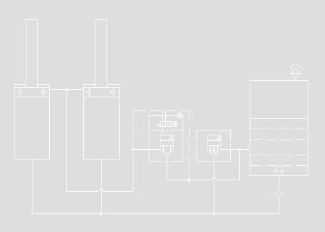
Hydraulic Schematic Diagram(a)
b---The opening grab is put on the bulk materials by the crane,loose the steel wire rope,the piston rod of the cylinder falls with the gravity of the transverse frame. The piston falls,at this moment,the hydraulic oil in the down space of the cylinder goes into the upper space via one-way valve on the piston.The redundant oil is pressed back to the oil tank.
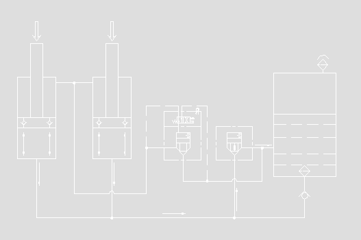
Hydraulic Schematic Diagram(b)
c---When the piston falls to the bottom of the cylinder,the hydraulic oil in the down space of the cylinder flows back to the oil tank via hose pipes,while the hydraulic oil in the upper space of the cylinder is connected to the solenoid valve and change cartridge valve via hose pipes,and the solenoid valve still locks.

Hydraulic Schematic Diagram(c)

Hydraulic Schematic Diagram(d)
d---Lift the steel wire rope,which drives the transverse frame to lift the through beam.The lifting force of the crane is transmitted to the grab head & piston via steel wire rope.The hydraulic oil cannot flow out for the hydraulic oil in the upper space of cylinder is locked,so the oil pressure is produced, which makes the oil cylinder and through beam go up together,the scoops close and is lifted c/w the steel wire rope. At this moment,the grab loads the materials and is lifted.
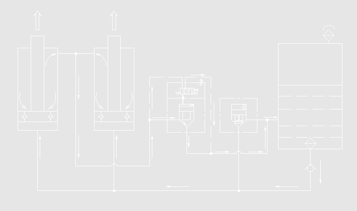
Hydraulic Schematic Diagram(e)
e---After the grab loads and is lifted to the destination via the crane. The operator press the button of the remote control,the transverse frame c/w the piston rod of the cylinder stand up to the grab head via the crane, and the through beam falls via the dead weight & pressure in the upper cavity of the oil cylinder releases.At this moment, the grab opens and unloads the materials.
The pressure oil reaches to the solenoid directional valve & change cartridge valve at the same time.For the solenoid directional valve reverses by having electricity,the pressure oil on the spool of the change cartridge valve is released,the spool of the change cartridge valve goes up,then the change cartridge valve is opened. All the pressure oil in the cylinder flows back to the oil tank via hose pipes & change cartridge valve.
When the oil returns in the upper cavity of the cylinder,the down cavity is vacuum,for the function of the air pressure & hydraulic oil in the tank,the oil in the tank flows into the one-way valve of the pipeline via the filter device,and finally arrives at the down cavity of the cylinder,the piston rod extends,finish the grab opening.
C.Operation Rules
1) When use the grab,the safety operation rules of the crane must be followed.
2)Wedge sets/Rope cramp should be checked before use, and their installation should be according to the technical requirements,if loose,please fasten in time.If the shackles deform, wedge sets crack,screws of the rope cramp damage,they should be changed.
3)Empty grab test should be carried on--all the turning parts should be flexible,grabs' opening & closing should be accurate and smooth.
4)To avoid damages to the grab,hit the materials/cranes/ship rails... in high speed is not allowed.
5)The balancing stand on the transverse frame should turn smoothly,and the steel wire rope should swing freely & keep horizontal when the grab is working.
6)The grab should be kept vertical when it is on the materials,which makes the transverse frame fall smoothly. To avoid causing large yawing force(this force will effect the resetting of the piston rod) to the piston rod by the transverse frame,for the big angle caused by grab's leaning.
7)All the turning axis pins,rope guide devices and bearings of the pulley should be added lubricant oil.
-Add lubricant oil before working.
-Add lubricant oil once at least after 24 hours continuously working.
-Add lubricant oil after finishing working each time.
When stop using,the grab should be washed cleanly,and materials in transverse frame & each turning part should be cleared away.The grab should be close if do not work in a long time.And all the joints should be add sufficient grease or lubricant oil.
8)To achieve the max.loading,the grab should work in the state of complete opening.The limit plate must keep touch,if the grab cannot close smoothly,should stop closing,then open the grab again to check if there are big blocks of the materials.
9)When change the batteries,to avoid the damage caused by loose,the fasteners must be fastened.
10)When use the new grab, the screws should be checked for every few hours.If loose,please fasten them in time.
11)When the grab need move/deliver,the piston rod should be extended completely.
D.Operation Requirements
1)Remote control grab is apply to loading & unloading bulk materials on the cranes with single lifting mechanism.
2)To avoid overload,the volume can be changable via the spill plates according to the density of different materials.To avoid overload caused by failed flow of the materials,the remote control grab with spill plates is not suitable for loading & unloading sticky bulk materials.
3)The storage batteries should be full.To guarantee the enough working time,the batteries should be recharged again if the full batteries are not used in three months.
4)Put the batteries into the batteries bin of the grab,tighten the fasteners and cover the bin gate,plug in the socket and turn on the power switch,after about one minute,the electric control system begin working.
5)The grab works according to the hydraulic schematic (a→b→c→d→e→a).
6)After working, the cylinders should extend completely,and please turn off the power,and keep the remote control well.
Remarks:
v When turning off the power,the cylinders are in the state of locking!!!
v The power should be turned off after the cylinders extend completely and the locater pin of transverse frame inserts the hole of through beam!!!


